Final "Pitch Perfect"
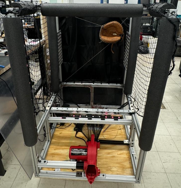
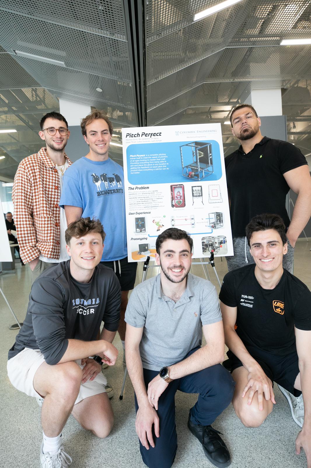
For my senior design project, me and a group of 5 Mechanical Engineer's built "Pitch Perfect", a 2 axis cable gantry system that can detect a baseball, move a glove to its position, and throw the ball back to the pitcher.
Create a Robotic Baseball catcher that can locate a ball, move a glove to "catch" the ball, and throw it back to the pitcher
For my senior design project, me and a group of 5 Mechanical Engineer's built "Pitch Perfect", a 2 axis cable gantry system that can detect a baseball, move a glove to its position, and throw the ball back to the pitcher.
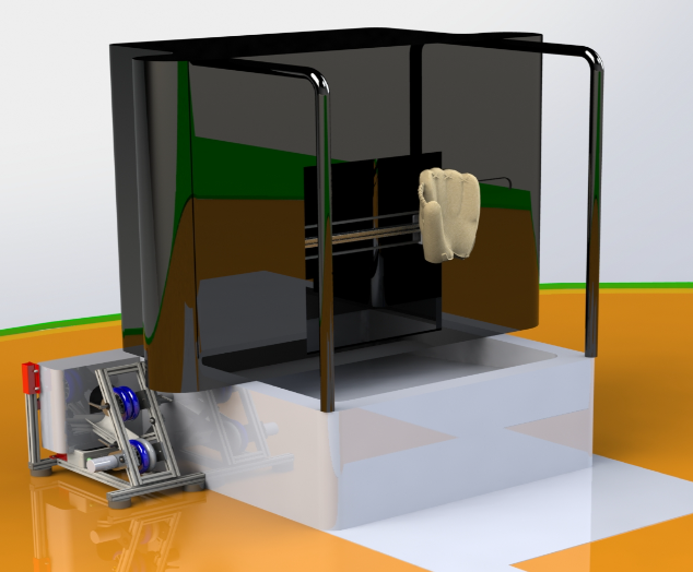
This is the first CAD of our project. Much like other pitching equipment, there is a target area for the pitcher to throw into, however in our design, the ball filters down into a ball launcher to get sent back to the pitcher, so they can avoid shagging.
In this model, you can see the housing take shape, the cable gantry system beginning to look more complete, and the location of the ball retrival system being finalized.
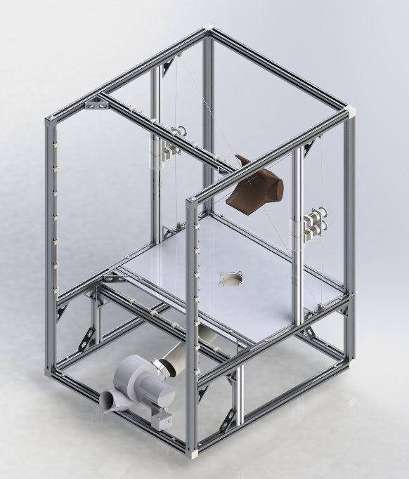
Here you can see the idea behind the gantry system. 4 stepper motors are connected to pulleys, which connect to know points on the glove. They will pull on the glove in such a way that it is always tensioned so the glove can move to the desired position.
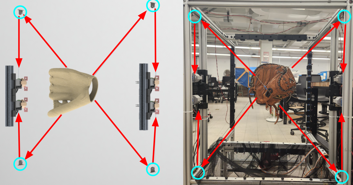
Here is another angle of the same system. An iterative design process lead to the group choosing closed loop controlled stepper drivers because we wanted to prevent the motors from losing their known position when the force of the baseball pulled on them via the glove.
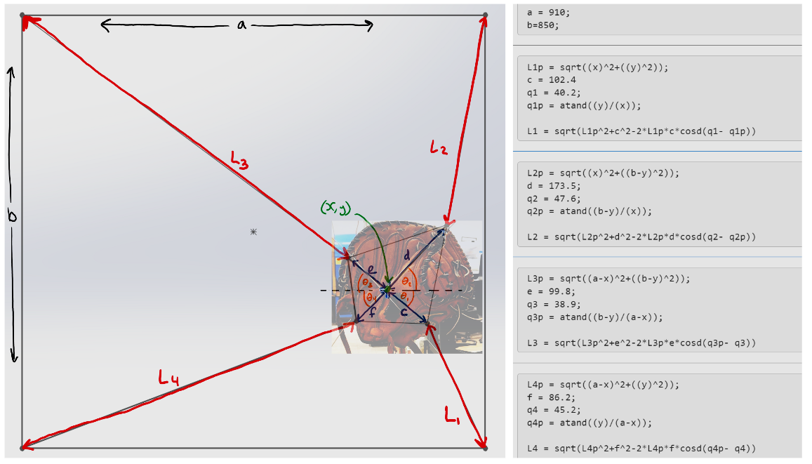
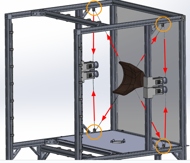
This photo shows the known connection points to the glove, and the resulting trignometry to move the glove to its ideal position.
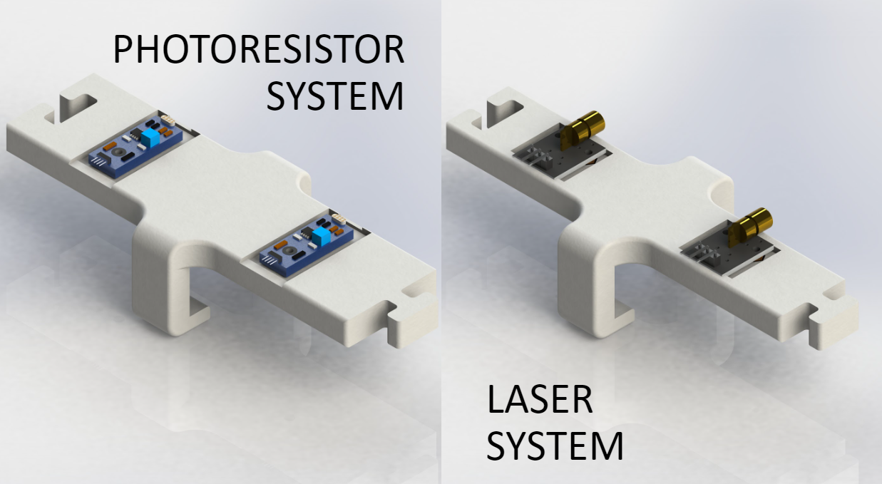
2 Lasers and 2 photo resistors will be lined up with each other in a space that is slightly smaller than a baseball. When the baseball crosses the lasers, the photo resistor will read a value of 0, and that 0 relative to other photo resistors reading 1 will indicate position.
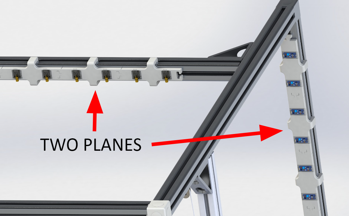
There are 2 grids of lasers, one in the horizontal and one in the vertical direction. They are spaced apart, so if you look at them straight on, they appear to be in a grid formation. The ball will break the first set of lasers, and then the second, and from this we can determine its relative position.
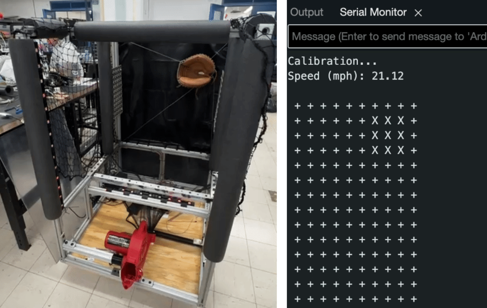
This is the final output of the Laser System. As you can see, the x's indicate a break in the system, which is where the baseball passed through the wall of lasers and photoresistors.
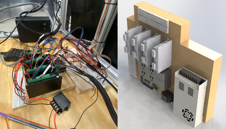
This build required both AC and DC power, DC power at 24 volts and 5 volts, as well as enough current to power the lasers, motors, ball retrival system, and Arduino. The circuit receives AC 110 volts from a wall outlet, and converts it to DC power using a power supply. It then uses a DC to DC converter to power all the 5 volt components, as well as an electronic relay to power the ball retrival system (the component that uses the most power) only when neccessary.
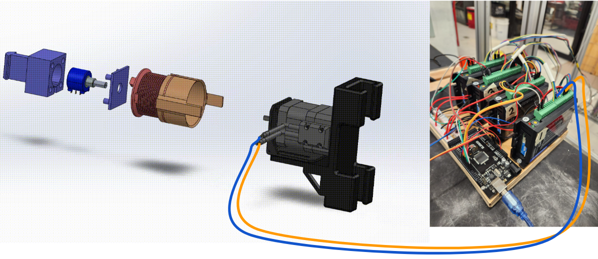
The pulley system has the stepper motors which are driven by the stepper drivers on the right in this photo. In addition, to maintain their relative position when the machine is not powered, they also turn 10k potentoimeters to physically keep their position. This is also connected to power so the signal is maintained.
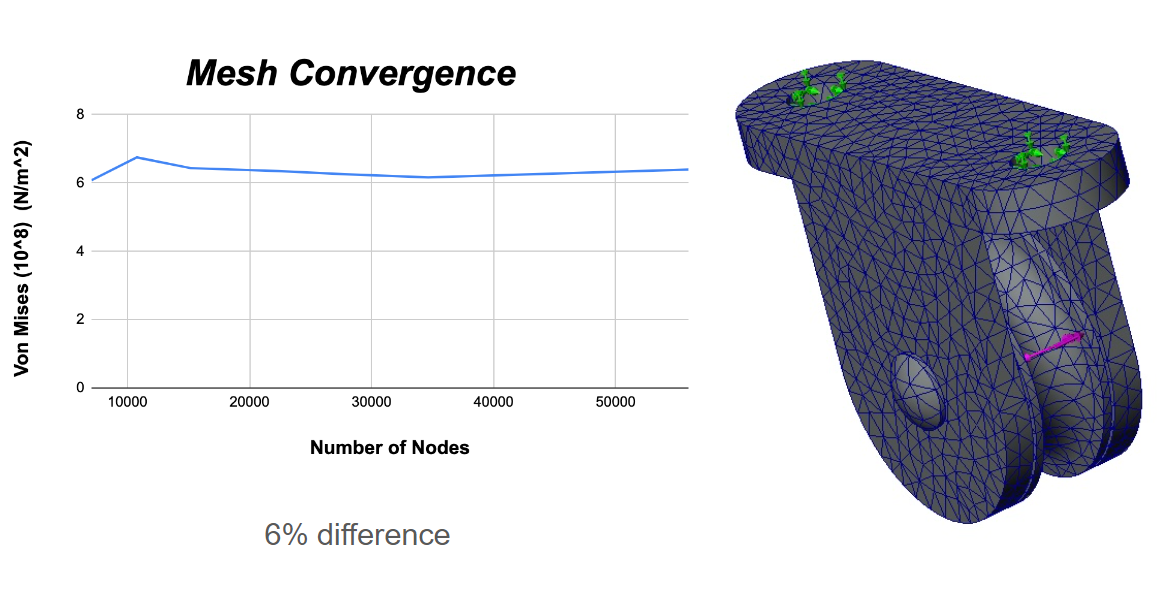
We wanted to perform FEA on the pulleys and aluminum extrusion housing tubes to ensure they had an adquete factor of safety. This first photo shows the mesh convergence of the pulley ensuring there aren't sharp corners that will derail the study.
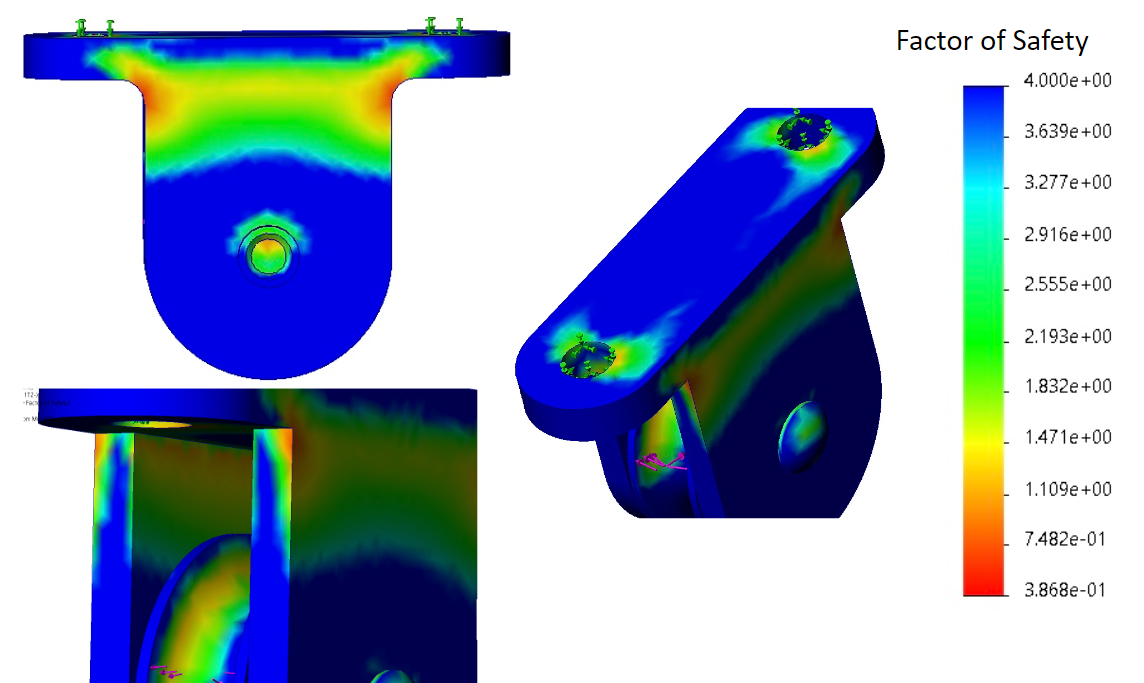
Here we can see the factor of safety plot for the pulley's. The stress concentrations looked similar to what we expected, and the range of values was close to what you would see from harder pitches.
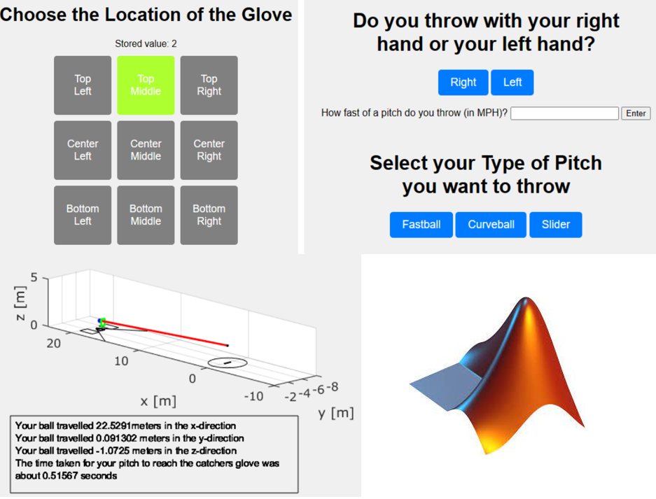
Here, I've developed an app that takes user input for speed, pitching hand, location, and type of pitch to generate a graphical representation of the ball's ideal trajectory as it reaches Pitch Perfect. A future iteration of this project aims to integrate the app with Pitch Perfect, displaying the ball's trajectory in real-time along with final stats.
Thank you for reading this far, here you can find a goofy pitch video for our product: ![]()